Line Support:
The supporting structures for overhead line conductors are various types of poles and towers called line support. In general, the line supports should have the following properties :
- High mechanical strength to withstand the weight of conductors and wind loads etc.
- Light in weight without the loss of mechanical strength.
- Cheap in cost and economical to maintain.
- Longer life,
- Easy accessibility of conductors for maintenance.
The line support used for transmission and distributions are of different types:
They are: (1) Electrical poles
(2) Electrical towers
(1) Electrical poles:
(a) Wooden pole
(b) Steel pole
(c) RCC pole
(2) Electrical tower:
(a) Tangent tower
(b) Angle tower
(c) Special tower
#Special tower are classified into following:
(a) River crossing tower
(b) Railway crossing tower
(c) Valley crossing tower
#On the basis of deviation towers are:
(1) A type (0-2degree)
(2) B type (2-6deg)
(3) C type (6-15deg)
(4) D type (15-30deg)
(5) E type (30-60deg)
#In all of above, Steel are used to manufacture all these towers:
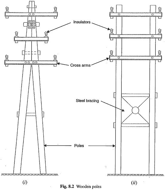
1.Wooden poles: These are made of seasoned wood (sal or chir) and are suitable for lines of moderate X-sectional area and of relatively shorter spans, say upto 50 metres. Such supports are cheap, easily available, provide insulating properties and, therefore, are widely used for distribution purposes in rural areas as an economical proposition The wooden poles generally tend to rot below the ground level, causing foundation failure. In order to prevent this, the portion of the pole below the ground level is impregnated with preservative compounds like creosote oil. Double pole structures of the ‘A’ or ‘H’ type are often used (See Fig. 8.2) to obtain a higher transverse strength than could be economically provided by means of single poles.
The main objections to wooden supports are :
- tendency to rot below the ground level
- comparatively smaller life (20-25 years)
- cannot be used for voltages higher than 20 kV
- less mechanical strength and
- require periodical inspection.
2.Steel poles: The steel poles are often used as a substitute for wooden poles. They possess greater mechanical strength, longer life and permit longer spans to be used. Such poles are generally used for distribution purposes in the cities. This type of supports need to be galvanised or painted in order to prolong its life. The steel poles are of three types viz.,
- rail poles
- tubular poles and
- rolled steel joints.
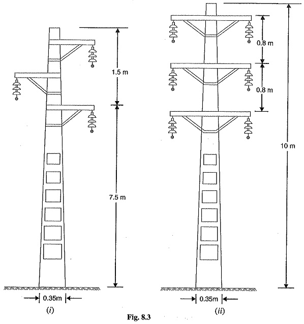
3.RCC poles: The reinforced concrete poles have become very popular as line support in recent years. They have greater mechanical strength, longer life and permit longer spans than steel Moreover, they give good outlook, require little maintenance and have good insulating properties. Fig. 8.3 shows R.C.C. poles for single and double circuit. The holes in the poles facilitate the climbing of poles and at the same time reduce the weight of line support.
The main difficulty with the use of these poles is the high cost of transport owing to their heavy weight. Therefore, such poles are often manufactured at the site in order to avoid heavy cost of transportation.
4.Steel towers: In practice, wooden, steel and reinforced concrete poles are used for distribution purposes at low voltages, say upto 11 kV. However, for long distance transmission at higher voltage, steel towers are invariably employed. Steel towers have greater mechanical strength, longer life, can withstand most severe climatic conditions and permit the use of longer spans. The risk of interrupted service due to broken or punctured insulation is considerably reduced owing to longer spans. Tower footings are usually grounded by driving rods into the earth. This minimizes the lightning troubles as each tower acts as a lightning conductor.
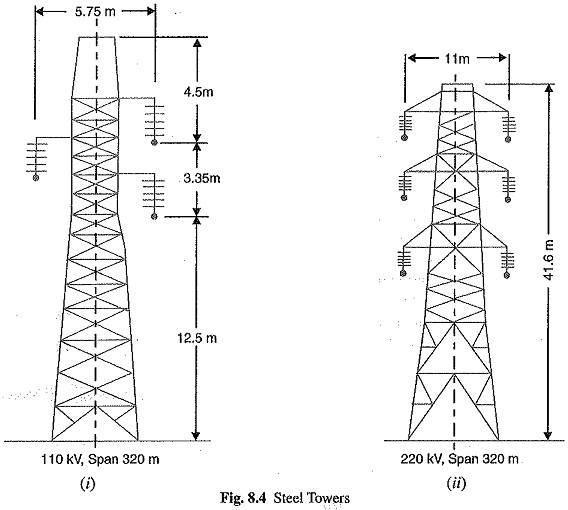
Fig. 8.4 (i) shows a single circuit tower. However, at a moderate additional cost, double circuit tower can be provided as shown in Fig. 8.4 (ii). The double circuit has the advantage that it ensures continuity of supply. It case there is breakdown of one circuit, the continuity of supply can be maintained by the other
circuit.


